Pages

Showing posts with label PLC. Show all posts

Saturday, August 18, 2007

Ladder Logic Programming

for Programmable Logic Controllers

What makes a PLC special? PLC's are used to automate machinery in assembly lines. For our project, we use the computer link feature that allows a PLC to take commands and communicate with a host computer. If something goes wrong with the computer link, the PLC still functions and protecting valuable equipment.

High Resolution Fly's Eye experiment, uses a Toshiba T1 PLC as part of a steerable laser system used for monitoring atmospheric clarity. We use a model TDR116-6S. The PLC was purchased as part of a starter kit. Specifically the PLC is used to open and close a cover that protects the a steering mechanism when the systems is not used. It is programmed to automatically close this cover after one hour unless it has received and instruction from the main PC to keep the cover open. This means that even if the PC or network communication to the site fails, the cover will still close. It is also used to power cycle equipment, including the laser and the radiometer.


This PLC and most others use a language called relay ladder logic programming. However, if you've programmed in high level languages before don't be fooled by that last part. Ladder logic is not necessarily difficult. Once you get the hang of it it isn't hard at all. But.. ladder logic is quite different from more common programming languages such as FORTRAN or c. It's true that ladder logic uses conditional statements, subroutines and FOR NEXT loops but there are some very significant differences.

Unlike FORTRAN or c, with ladder logic, every 'rung' of the code is multithreaded. Normally in a programming language things happen in order. The command or line of code on top is executed before the command on the bottom until you hit the end of a loop. This is not so in ladder logic. Everything happens at the same time.

So what is ladder logic programming really like? Ladder logic programming looks, well, like a ladder. It's more like a flow chart than a program. There are two vertical lines coming down the programming environment, one on the left and one on the right. Then, you have rungs of conditionals on the left that lead to outputs on the right. For example:


x0001 x0002 Y0001
|---| |-----|/|---------( )-----|
| |
| |
| x0001 Y002 |
|---| |--[01000 TON T012]--( )--|
| |
| |
| R001 |
|--[D0140 = 0001]--------( )--|
| |
| R001 Y004 |
|--| |---------------------( )--|
| |
|-{END}-------------------------|

In Ladder logic programming you do not have variables, you have registers. There are four kinds of registers: X's that are inputs, Y's that are outputs, D's that are data that can form interger, hex and real numbers, and finally R's that are internal relays. X's and Y's are pointers to the actual terminal strip connectors (what you use a screw driver on to connect wires) on the PLC. If you energize an input, let's say 5, then X0005 will have an on status; also if you give Y0023 an on status then relay 23 will flick on. R's are just about the same as X's and Y's except that they don't point to any hardware. They just hold an on or off value inside of the PLC's memory. R's can be useful. X's Y's and R's can even hold data besides their on and off states on many PLC's, but personally I don't recommend it. For data like integers and hexadecimal numbers D's are used as their addresses.

example one. The things you will probably use the most writing Ladder Logic are the relay conditionals --| |-- ---|/|--- and the output coils ---( )---. These three things basically make up a kind of IF THEN statement. This --| |-- means closed if energized while --|/|-- means closed if not energized. The output coil --( )-- basically means then energize this. So the first rung of example one means that if input 1 is energized and input 2 is not then energize output 1. You should note that on the T1, the number of a particular input or output is written on the case of the PLC but for T2's and for some other more advanced PLC's this is not necessarily the case. To find out what the addresses of your inputs and outputs are you should refer to the documentation that came with your PLC. Also, in most ladder logic programming environments you have to specify the address of each of your inputs and outputs before it will even let you start programming. [the T series can auto configure]

delay timer. What this means is that after a specified amount of time after x0001 turns on, y0002 will turn on. You should note that because of the nature of ladder logic you can not simply put a timer attached directly to the left hand side without a relay conditional between it. Remember, everything is happening at the same time. PLC's are meant to run on their own for long periods of time, so you can't just tell it that 10 seconds after it's first plugged in it should activate something. You have to tell it to start timing after something in the outside world has occurred, like the energizing or de-energizing of an input.

In the code --[01000 TON T012]-- there is the parameter 01000 that tells the timer to wait 1000*10ms or 10 seconds, and the parameter T012 tells the PLC which internal timer you want to use. Some of the more advanced PLC's have timers with different accuracy. Most measure time in 10ms intervals but others measure time in single milliseconds. You should check the documentation on your PLC to see if any of it's timers measure time in different units than the others. Also you should not use the same timer for more than one thing.

On rung three of the ladder we have a conditional statement. If the number stored in D0140 is equal to 1 then energize R001. If you look at the entire circuit you'll note that there is no where else in it where D0140 is mentioned and you should know that all data registers are set to 0 at default. You may think that D0140 will never actually reach the value of 1 and that R001 will never be activated and that rung three and four are useless garbage code. It's true that during the normal operation of the PLC D0140 will never change from zero and the last two rungs before end would be useless. However, this is where the computer link function comes in. All Toshiba PLC's have a computer link protocol built into them. This allows a host computer, such as any sort of DOS, Linux based PC or even a Unix administrator with an RS232 serial port to send commands to the PLC while it's running and read or write values into its registers. This includes data, inputs, outputs, and relays.

Suppose that Y004 was attached to equipment that you wanted to turn it on or off at your pleasure. Suppose it was an air conditioner or maybe some strange contraption that brought you a coke from the fridge to your seat at a computer. If you can write a program at your own specialized system that can send ASCII characters with 8 data bits 1 start bit 1 stop bit and 9600 baud rate with odd parity, then you can manipulate the registers in the Toshiba PLC's and toggle d0140 between 1 and zero or 1 and any other value. See more about the computer link function with a sample C program written under Linux latter. C example

The final rung on the ladder the -{END}- is basically what it says. It's the end statement. It doesn't really do anything except to say, well, your done programming. However, no program will work without an end statement and the PLC will ignore any code put in after an end statement. This shouldn't be a problem for small programs, just look at the screen and make sure the end is in there and at the bottom. If you happen to be making a very large and a very complicated relay circuit your editor will likely force you to write it in separate blocks. Before attempting to write a very large program you should go to the very last programming block available to you and put the end statement there and no where else. The end statement can be used in debugging by ending the program early and disabling commands that fall after the end statement.


| X001 Y001 Y001 |
|-| |---|/|---[01000 TON T002]-[01000 TOF T003]---------( )--| rung one
| |
| X001 Y002 |
|--| |----+---------------------------------------------( )--| rung two
| | |
| Y002 | |
|--| |----+ |
| X001 R006 |
|--| |--|/|--[01000 TON T004]-----+-------[D150 + 1 -> D150]-| rung three
| | R006 |
| +---[01000 TOF T005]--( )--|
| |
| Y003 |
|-[D150 >200]-------------------------------------------( )--| rung four
| |
| Y003 |
|-| |-----------------------------------------[ 0 MOV D150]--| rung five
| |
|--{END}-----------------------------------------------------| END rung

Example two is a bit more complicated than example one, but once you understand it you'll be on your way to being able to design your own relay ladder logic. Rung one is especially interesting. A TON and a TOF combination that lets output Y001 cycle on and off for 10 seconds at a time. While TON waits a given time before allowing an energized input to affect an output, TOF waits a given time before de-energizing an output after it's input has been cut off.

Let's analyze the rung. The -| |- conditional with X001 is there for good programming, it isn't actually necessary in this rung but if it's not there you have no way to stop the oscillating of Y001 during the PLC's operation. Now notice that we're not allowing current to flow if Y001 is energized yet the output of this rung is to energize Y001. Well, if Y001 is off then current is passed to TON. After TON has gone through it's specified time it will energize Y001. Now that Y001 is energized current to the rung is cut off. Once the current has stopped TOF will keep Y001 powered for a specified amount of time before Y001 feels the affects and de-energizes. With Y001 de-energized TON is energized again and the cycle goes on. (You may want to reread that last sentence a few times) The output Y001 stays on for a second, then off for a second continuously cycling.

Rung two shows how to set up a push button. With a momentary push button, the input is only energized for a short amount of time, but often it is useful to keep the rung on long afterwards. What you should notice about rung two is that the output is connected to the left hand side twice. If either of the two relay conditionals are on, then the output is on. Notice that one of the relay conditionals is the output itself. Thus if the output is powered for just one of the PLC's cycles (a very short time) then the output's own momentary on state will keep itself energized. You want to put in an internal relay conditional between the Y002 input and output or else you'll never be able to get it off! Well you could if you restart the PLC's program or with the computer link protocol.

Rung three is also spread across two rung slots but you could get it on one rung if it would fit ( it really doesn't all fit on one rung in the editor). It's basically like rung one except that between the timers is a data statement that increments D150 by one. There are other ways to increment a data register, but this is what I used. Because it's between the timers, the data function will only get power and operate once during the period of the cycle. Since most of the timers only measure in milliseconds you can use a rung like this to measure time in hours or days if your PLC doesn't have any function that will do it for you.

Rung four simply turns on an output when D150 is greater than a number i.e. a certain amount of time has gone by.

Rung five sets D150 back to 0 when that output has been on momentarily. In a real application of something like this you'd probably want to use a TOF on rung four so that when D150 is no longer greater than 200 Y003 will wait a moment before deactivating, other wise it will deactivate after one cycle of the PLC. The PLC probably goes through around a thousand cycles per second. A cycle is when the PLC updates the on, off, and value states of the relays and registers.

You should notice that I didn't just say D150=0. The = sign is already used in conditionals so instead you have to use a move command. The --[0 MOV D150]-- means move the value of 0 into the register D150. There are many other data functions and ladder logic components that you can use. So far I've only gone over what I think are the most important ones. For example, the T1 also haws its own counters and flip flop's built in to use in your program. Don't be afraid to experiment for your self though. When you buy the starter kit a you get PLC, a ladder logic editor and documentation including a list of all of the programming components, hardware, and exactly how everything works.

http://xtronics.com/toshiba/Ladder_logic.htm

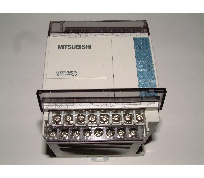
PLC pic :


PLC Rack

Sunday, August 5, 2007

Programmable logic controller

From Wikipedia, the free encyclopedia

A Programmable Logic Controller, PLC, or Programmable Controller is a digital computer used for automation of industrial processes, such as control of machinery on factory assembly lines. Unlike general-purpose computers, the PLC is designed for multiple inputs and output arrangements, extended temperature ranges, immunity to electrical noise, and resistance to vibration and impact. Programs to control machine operation are typically stored in battery-backed or non-volatile memory. A PLC is an example of a real time system since output results must be produced in response to input conditions within a bounded time, otherwise unintended operation will result.

Features

The main difference from other computers is that PLC are armored for severe condition (dust, moisture, heat, cold, etc) and have the facility for extensive input/output (I/O) arrangements. These connect the PLC to sensors and actuators. PLCs read limit switches, analog process variables (such as temperature and pressure), and the positions of complex positioning systems. Some even use machine vision. On the actuator side, PLCs operate electric motors, pneumatic or hydraulic cylinders, magnetic relays or solenoids, or analog outputs. The input/output arrangements may be built into a simple PLC, or the PLC may have external I/O modules attached to a computer network that plugs into the PLC.
PLCs were invented as replacements for automated systems that would use hundreds or thousands of relays, cam timers, and drum sequencers. Often, a single PLC can be programmed to replace thousands of relays. Programmable controllers were initially adopted by the automotive manufacturing industry, where software revision replaced the re-wiring of hard-wired control panels when production models changed.
Many of the earliest PLCs expressed all decision making logic in simple ladder logic which appeared similar to electrical schematic diagrams. The electricians were quite able to trace out circuit problems with schematic diagrams using ladder logic. This program notation was chosen to reduce training demands for the existing technicians. Other early PLCs used a form of instruction list programming, based on a stack-based logic solver.
The functionality of the PLC has evolved over the years to include sequential relay control, motion control, process control, distributed control systems and networking. The data handling, storage, processing power and communication capabilities of some modern PLCs are approximately equivalent to desktop computers. PLC-like programming combined with remote I/O hardware, allow a general-purpose desktop computer to overlap some PLCs in certain applications.
Under the IEC 61131-3 standard, PLCs can be programmed using standards-based programming languages. A graphical programming notation called Sequential Function Charts is available on certain programmable controllers.

PLC compared with other control systems


PLCs are well-adapted to a certain range of automation tasks. These are typically industrial processes in manufacturing where the cost of developing and maintaining the automation system is high relative to the total cost of the automation, and where changes to the system would be expected during its operational life. PLCs contain input and output devices compatible with industrial pilot devices and controls; little electrical design is required, and the design problem centers on expressing the desired sequence of operations in ladder logic (or function chart) notation. PLC applications are typically highly customized systems so the cost of a packaged PLC is low compared to the cost of a specific custom-built controller design. On the other hand, in the case of mass-produced goods, customized control systems are economic due to the lower cost of the components, which can be optimally chosen instead of a "generic" solution, and where the non-recurring engineering charges are spread over thousands of sales.
For high volume or very simple fixed automation tasks, different techniques are used. For example, a consumer dishwasher would be controlled by an electromechanical cam timer costing only a few dollars in production quantities.
A microcontroller-based design would be appropriate where hundreds or thousands of units will be produced and so the development cost (design of power supplies and input/output hardware) can be spread over many sales, and where the end-user would not need to alter the control. Automotive applications are an example; millions of units are built each year, and very few end-users alter the programming of these controllers. However, some specialty vehicles such as transit busses economically use PLCs instead of custom-designed controls, because the volumes are low and the development cost would be uneconomic.
Very complex process control, such as used in the chemical industry, may require algorithms and performance beyond the capability of even high-performance PLCs. Very high-speed or precision controls may also require customized solutions; for example, aircraft flight controls.
PLCs may include logic for single-variable feedback analog control loop, a "proportional, integral, derivative" or "PID controller." A PID loop could be used to control the temperature of a manufacturing process, for example. Historically PLCs were usually configured with only a few analog control loops; where processes required hundreds or thousands of loops, a distributed control system (DCS) would instead be used. However, as PLCs have become more powerful, the boundary between DCS and PLC applications has become less clear-cut.

Digital and analog signals

Digital or discrete signals behave as binary switches, yielding simply an On or Off signal (1 or 0, True or False, respectively). Pushbuttons, limit switches, and photoelectric sensors are examples of devices providing a discrete signal. Discrete signals are sent using either voltage or current, where a specific range is designated as On and another as Off. A PLC might use 24 V DC I/O, with values above 22 V DC representing On and values below 2VDC representing Off. Initially, PLCs had only discrete I/O.
Analog signals are like volume controls, with a range of values between zero and full-scale. These are typically interpreted as integer values (counts) by the PLC, with various ranges of accuracy depending on the device and the number of bits available to store the data. As PLCs typically use 16-bit signed binary processors, the integer values are limited between -32,768 and +32,767. Pressure, temperature, flow, and weight are often represented by analog signals. Analog signals can use voltage or current with a magnitude proportional to the value of the process signal. For example, an analog 4-20 mA or 0 - 10 V input would be converted into an integer value of 0 - 32767.
Current inputs are less sensitive to electrical noise (i.e. from welders or electric motor starts) than voltage inputs.

Example

As an example, say the facility needs to store water in a tank. The water is drawn from the tank by another system, as needed and our example system must manage the water level in the tank.
Using only digital signals, the PLC has two digital inputs from float switches (tank empty and tank full). The PLC uses a digital output to open and close the inlet valve into the tank.
If both float switches are off (down) or only the 'tank empty' switch is on, the PLC will open the valve to let more water in. If only the 'tank full' switch is on, the valve turns off. Both switches being on would signal that something is wrong with one of the switches, as the tank cannot be both full and empty at the same time. Two float switches are used to prevent a 'flutter' condition where any water usage activates the pump for a very short time causing the system to wear out faster.
An analog system might use a load cell (scale) that weighs the tank, and an adjustable (throttling) valve. The PLC could use a PID feedback loop to control the valve opening. The load cell is connected to an analog input and the valve is connected to an analog output. This system fills the tank faster when there is less water in the tank. If the water level drops rapidly, the valve can be opened wide. If water is only dripping out of the tank, the valve adjusts to slowly drip water back into the tank.
In this system, to avoid 'flutter' adjustments that can wear out the valve, many PLCs incorporate "hysteresis" which essentially creates a "deadband" of activity. A technician adjusts this deadband so the valve moves only for a significant change in rate. This will in turn minimize the motion of the valve, and reduce its wear.
A real system might combine both approaches, using float switches and simple valves to prevent spills, and a rate sensor and rate valve to optimize refill rates. Backup and maintenance methods can make a real system very complicated.

System scale


A small PLC will have a fixed number of connections built in for inputs and outputs. Typically, expansions are available if the base model does not have enough I/O.
Modular PLCs have a chassis (also called a rack) into which is placed modules with different functions. The processor and selection of I/O modules is customised for the particular application. Several racks can be administered by a single processor, and may have thousands of inputs and outputs. A special high speed serial I/O link is used so that racks can be distributed away from the processor, reducing the wiring costs for large plants.
PLCs used in larger I/O systems may have peer-to-peer (P2P) communication between processors. This allows separate parts of a complex process to have individual control while allowing the subsystems to co-ordinate over the communication link. These communication links are also often used for HMI (Human-Machine Interface) devices such as keypads or PC-type workstations. Some of today's PLCs can communicate over a wide range of media including RS-485, Coaxial, and even Ethernet for I/O control at network speeds up to 100 Mbit/s.

Programming


Early PLCs, up to the mid-1980s, were programmed using proprietary programming panels or special-purpose programming terminals, which often had dedicated function keys representing the various logical elements of PLC programs. Programs were stored on cassette tape cartridges. Facilities for printing and documentation were very minimal due to lack of memory capacity. More recently, PLC programs are typically written in a special application on a personal computer, then downloaded by a direct-connection cable or over a network to the PLC. The very oldest PLCs used non-volatile magnetic core memory but now the program is stored in the PLC either in battery-backed-up RAM or some other non-volatile flash memory.
Early PLCs were designed to be used by electricians who would learn PLC programming on the job. These PLCs were programmed in "ladder logic", which strongly resembles a schematic diagram of relay logic. Modern PLCs can be programmed in a variety of ways, from ladder logic to more traditional programming languages such as BASIC and C. Another method is State Logic, a Very High Level Programming Language designed to program PLCs based on State Transition Diagrams.
Recently, the International standard IEC 61131-3 has become popular. IEC 61131-3 currently defines five programming languages for programmable control systems: FBD (Function block diagram), LD (Ladder diagram), ST (Structured text, similar to the Pascal programming language), IL (Instruction list, similar to assembly language) and SFC (Sequential function chart). These techniques emphasize logical organization of operations.
While the fundamental concepts of PLC programming are common to all manufacturers, differences in I/O addressing, memory organization and instruction sets mean that PLC programs are never perfectly interchangeable between different makers. Even within the same product line of a single manufacturer, different models may not be directly compatible.

User interface

PLCs may need to interact with people for the purpose of configuration, alarm reporting or everyday control. A Human-Machine Interface (HMI) is employed for this purpose.
A simple system may use buttons and lights to interact with the user. Text displays are available as well as graphical touch screens. Most modern PLCs can communicate over a network to some other system, such as a computer running a SCADA (Supervisory Control And Data Acquisition) system or web browser.

Communications

PLCs usually have built in communications ports usually 9-Pin RS232, and optionally for RS485 and Ethernet. Modbus or DF1 is usually included as one of the communications protocols. Others' options include various fieldbuses such as DeviceNet or Profibus. Other communications protocols that may be used are listed in the List of automation protocols.

History

The PLC was invented in response to the needs of the American automotive industry. Before the PLC, control, sequencing, and safety interlock logic for manufacturing automobiles was accomplished using relays, timers and dedicated closed-loop controllers. The process for updating such facilities for the yearly model change-over was very time consuming and expensive, as the relay systems needed to be rewired by skilled electricians. In 1968 GM Hydramatic (the automatic transmission division of General Motors) issued a request for proposal for an electronic replacement for hard-wired relay systems.
The winning proposal came from Bedford Associates of Bedford, Massachusetts. The first PLC, designated the 084 because it was Bedford Associates eighty-fourth project, was the result. Bedford Associates started a new company dedicated to developing, manufacturing, selling, and servicing this new product: Modicon, which stood for MOdular DIgital CONtroller. One of the people who worked on that project was Dick Morley, who is considered to be the "father" of the PLC. The Modicon brand was sold in 1977 to Gould Electronics, and later acquired by German Company AEG and then by Schneider Electric, the current owner.
One of the very first 084 models built is now on display at Modicon's headquarters in North Andover, Massachusetts. It was presented to Modicon by GM, when the unit was retired after nearly twenty years of uninterrupted service.
The automotive industry is still one of the largest users of PLCs, and Modicon still numbers some of its controller models such that they end with eighty-four. PLCs are used in many different industries and machines such as packaging and semiconductor machines. Well known PLC brands are Allen-Bradley, Mitsubishi Electric, ABB Ltd., Koyo, Honeywell, Siemens, Modicon, Omron, General Electric and Panasonic (a brand name of Matsushita).
In a similar way that Linux has changed personal and business computing there is an effort to bring Linux to the PLC world. With many challenges to overcome, the Linux open source PLC project is being worked on around the world. See the link below.

Other link
PLC Tutor

Article from "http://en.wikipedia.org/wiki/Programmable_logic_controller"